System designers have a bifurcated relationship with battery cells based on lithium chemistries. On one side, they appreciate and need the high energy density by weight and volume offered by these cells. On the other side, they’re aware of the very careful management required by these cells and their potential for thermal runaway (TR), fire, and even explosion due to internal defects.
To better understand the dynamic characteristics of lithium-ion (Li-ion) cells, a multi-organizational NASA team has developed a calorimeter that goes far beyond their basic role of measuring the heat flow of a chemical reaction or physical change. The NASA calorimeter is able to measure the total heat generated when specific types of Li-ion cells are deliberately driven into a runaway condition—and contain the resultant physical damage while also analyzing the thermal details and tangible debris (called “ejecta”).
By understanding the behavior of a Li-ion battery in this mode, designers can greatly improve modeling and statistical confidence associated with cell performance. Furthermore, they can strengthen cell and battery-pack casings to contain or reduce damages experienced during thermal runaway.
The need for the calorimeter was initially instigated by NASA’s interest in the Li-ion battery problems of the electrified Boeing 787 Dreamliner (2013), which grounded the aircraft family for months (totally unrelated to the current 737 MAX flight-control issues that have grounded all 737 MAX aircraft for a year). The Dreamliner issue was resolved by, among other tactics, design and installation of a special battery-containment box and smoke-venting system (see here). Of course, NASA’s use of Li-ion cells goes figuratively and literally far beyond the Dreamliner issues due to the use of Li-ion cells in many spacecraft.
Setting the Guidelines
To start, the NASA team established the criteria used to define success and began with the assumption that thermal runaway (TR) will always eventually happen. The design should ensure that the TR event is not catastrophic and demonstrate that propagation to surrounding non-TR cells will not occur.
They next defined multiple goals:
- The thermal-management system should mitigate the effects of TR and prevent cell-to-cell propagation by assuming that no two runaway events are the same and there’s a range of possible outcomes—even for cells from the same manufacturer and state-of-charge.
- Onset temperature, acceleration temperature, trigger temperature, trigger-cell peak temperature and neighbor-cell peak temperature are all variables.
- They should consider the type of cell failure (such as side wall vs. top), system pressure increase, gases released, and ejecta.
Therefore, a successful design optimization would need to know three things: total energy-output range during TR for a single Li-ion cell; fraction of TR energy transferred through the cell casing; and fraction of TR energy ejected through cell vent/burst paths.
Finally, the NASA team determined that the ideal calorimeter would need to provide three main features:
- Rapid triggering of thermal runaway, representative of field failure (such as failures that occur at room temperature).
- Rapid testing of multiple cells with minimal turnaround time to allow collection of a statistically significant data set (many tests per day).
- A means of separately tallying the heating contributions due to vented effluents and heating conducting from and/or convecting and radiating from the cell casing.
A review showed that each of the leading available calorimetry approaches—including accelerating-rate calorimetry (ARC), bomb calorimetry, and copper-slug Calorimetry—had one or more shortcomings such that they would not be able to provide the needed assessments.
FTRC Method
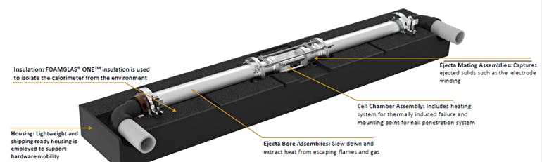
Consequently, the devised a new fractional TR calorimetry (FTRC) method for the popular, widely used 18650-size Li-ion cell (18 mm diameter by 65 mm long, slightly larger than a standard AA cell) (Fig. 1). The calorimeter has at least two chambers: one for the battery cell under test and one (or more) for receiving the ejecta resulting from thermal runaway. Both chambers are structurally strong and thermally insulated.
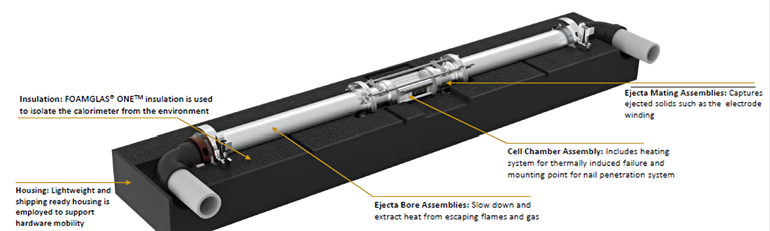 1. The new calorimeter design allows for discernment between the total heat output and the fraction of heat released through the cell casing versus ejecta material; the energy distributions are determined by post-processing temperature versus time for each calorimeter sub-assembly. It also accommodates cell designs with bottom vents (BVs); uses high flux heaters to initiate TR quickly; has a simple operation that enables multiple experiments per day; and is compatible with high speed X-ray videography. (Source: NASA)
When the test cell is intentionally driven into thermal runaway, the debris explodes into the ejecta chamber and is decelerated and collected. Thermal sensors are strategically placed throughout the chambers to collect thermal data during the test. Customized software analyzes the thermal data and determines key calorimeter parameters with a high degree of accuracy.
The calorimeter chamber itself is a complicated assembly (Fig. 2).
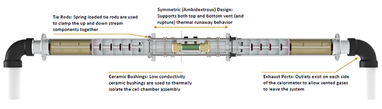 2. The cell chamber assembly is isolated from the remainder of the up- and down-stream calorimeter components with low conductivity ceramic bushings. Maintaining this thermal isolation is critical to providing the ability to discern the fraction of energy released through the cell casing versus through the ejecta material. (Source: NASA)
Each internal facet is intended to address a specific aspect of the TR considerations (Fig. 3).
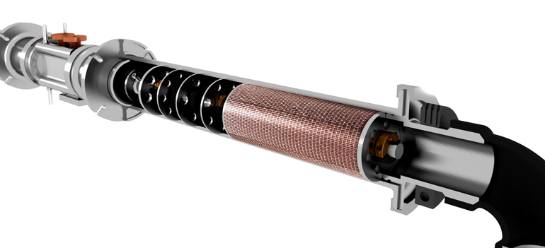 3. The internal baffles and copper mesh are used to create a tortuous path that effectively reduces flow velocity, captures large and fine ejected particulates, and cools down the flowing particles and gases before they exit the system (it captures the energy). (Source: NASA)
They used an internal short-circuiting (ISC) device that utilizes a wax with low melting point to create, on-demand, an internal short circuit between the Al positive-current collector and the graphite negative electrode’s surface. This trigger was deemed to be superior to more-obvious approaches, such as use of a nail puncture or surface heating.
In the first case, the nail acts as a heat sink, spreading the short circuit across a large area and creating an additional path for pressure relief. In the second, surface heating makes it hard to control exactly where thermal runaway will initiate, requires additional space and wiring, affects the structural integrity of the casing, and takes minutes of heating to reach the critical temperature of thermal runaway, providing more time for the electrode assembly to dry.
In their tests, they implanted the ISC device into three 18650 cell designs: one standard, one with a bottom vent, and one with a thicker casing. In their extensive study of 228 cells, the position at which thermal runaway initiates is shown to greatly affect the tendency of cells to rupture and incur side-wall breaches at specific locations. Beyond the obvious test instrumentation, they used high-speed synchrotron X-ray imaging at 2000 frames/s; image-based 3D thermal-runaway computational models can decouple the heat from ejected and non-ejected contents.
The NASA test setup (Fig. 4) enabled data collection and analysis yielded insights across multiple dimensions. These included characterization of total energy release; understanding of the nonlinear relationship between stored electrochemical energy and the total energy released, which is a function cell physical variables; and the thermal energy release fractions (material, direction, and much more) are determined for every cell configuration tested.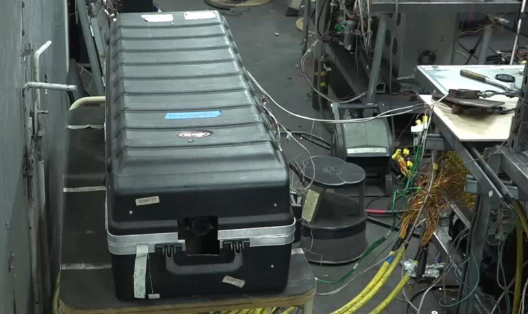 4. Part of the test setup at NASA Johnson Space Center Energy Systems Test Area (ESTA) shows the protective box enclosing the energy-laden calorimeter with internal cells that will undergo thermal runaway. (Source: NASA)
The results of their tests have too many parameters to summarize in just a few generalizations and give special insight into the heat generated by the ejected and non-ejected contents of the cells. However, details of the project including rationale, limitations of existing approaches, design of the calorimeter, test methods, and results are available via published papers such as:
[“source=digitalelectronics”]